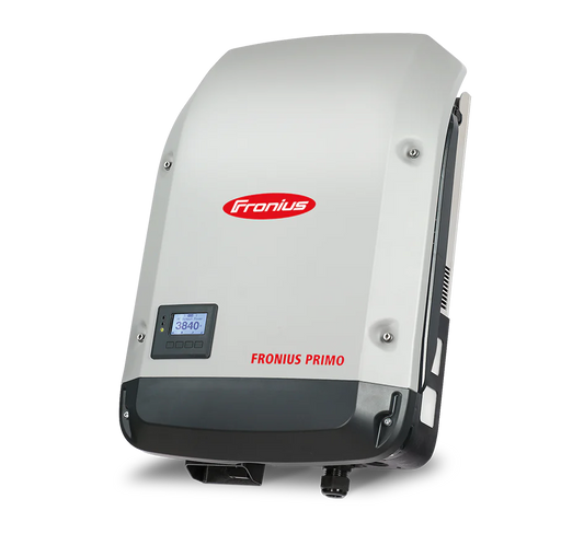
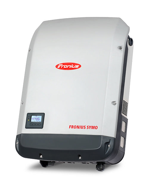
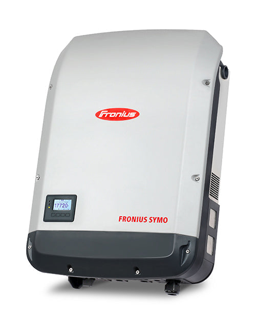
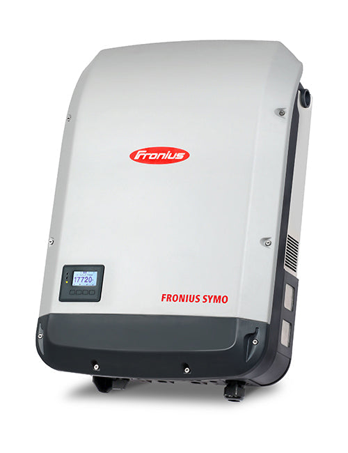
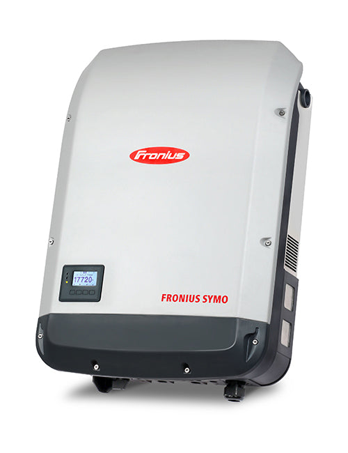
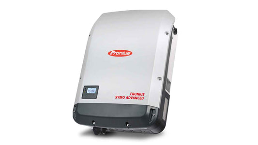
Fronius - Symo Advanced 15.0-3-480 - Lite

$4,222.00 USD
$4,503.00 USD
Sale
-6%
Start-EComposer-custom-liquid-pickup

Pickup available at Warehouse Canada

Usually ready in 5+ days

Fronius - Symo Advanced 15.0-3-480 - Lite

  • Warehouse Canada

    Pickup available, usually ready in 5+ days

    77 Martin Ross Ave
    North York ON M3J 2L5
    Canada

    +18444487664

End-EComposer-custom-liquid-pickup

Product details

Technical data

Talk to an expert

Video

Reviews

FAQ

DESCRIPTION

Product Description:

**Due to volatility of Fronius supply we cannot guarantee delivery date. 

Fronius - Symo Advanced 15.0-3-480 - Lite

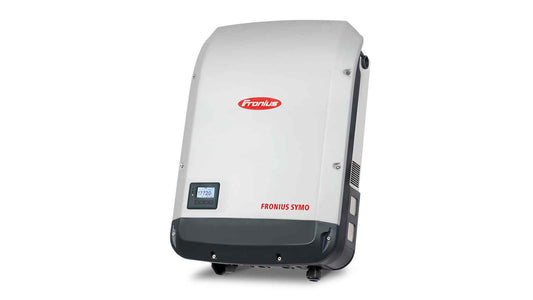
Boasting power categories from 10 to 24 kW, the transformerless Fronius Symo is the ideal compact three-phase inverter for commercial applications. Its dual maximum power point tracking, high maximum system voltage, wide input voltage range and unrestricted use indoors and out, ensures maximum flexibility in PV system design. As a member of the new SnapINverter family, the Fronius Symo features the SnapINverter mounting system, allowing for secure and convenient installation and field servicing.
 
Industry-leading features now come standard with the Fronius Symo, including: arc fault protection, integrated wireless monitoring, and SunSpec Modbus interfaces for seamless monitoring and datalogging via Fronius’ online and mobile platform, Fronius Solar.web. This makes the Fronius Symo one of the most communicative, efficient and streamlined inverters on the market. 


Specifications

SPECS

Power Output 15kW
AC Voltage 480V
DC Voltage 1000V
Peak Efficiency 0.98
CEC Efficiency 0.97
Maximum DC Input Voltage 1000V
Maximum Operation DC Input Current 2x33/25A
Number of MPPT's 2
MPP operating voltage window 200-1000V
Rated MPP voltage window for nameplate output power 350-800V
Connectivity WIFI/Ethernet


Dimensions

Shipping Dimensions

Weight: 96.00 LBS
Width: 51.00 (cm)
Height: 23.00 (cm)
Depth: 72.00 (cm)


INPUT DATA

Number of MPP trackers2

Max. input current (Idc max)

33,0 / 27,0 A

Max. short circuit current, module array*

68,0 / 56,0 A

DC input voltage range (Udc min - Udc max)

200 - 1000 V

Feed-in start voltage (Udc start)

200 V

Nominal input voltage (Udc,r)

600 V

MPP voltage range (Umpp min - Umpp max)

320 - 800 V
Usable MPP voltage range200 - 800 V
Number of DC connections3 + 3

Max. PV generator power (Pdc max) 

22,5 kWpeak

OUTPUT DATA

AC nominal output (Pac,r)

15 kW

Max. output power (Pac max)

15 kVA

AC output current (Iac nom)

21,7 A

Grid connection (Uac,r)

3~ NPE 400/230, 3~ NPE 380/220 V

AC voltage range (Umin - Umax)

150 - 280 V

Frequency (fr)

50 / 60 Hz

Frequency range (fmin - fmax)

45 - 65 Hz
Total harmonic distortion1,5 %

Power factor (cos φac,r)

0 - 1 ind,/cap,

GENERAL DATA

Width

510 mm

Height

725 mm

Depth

225 mm
Weight43,4 kg
Degree of protectionIP 66
Protection class1

Overvoltage category (DC / AC) 1)

2 / 3
Night-time consumption< 1 W
Inverter designTransformerless
CoolingRegulated air cooling
InstallationIndoors and outdoors
Ambient temperature range-40°C - +60°C
Permitted humidity0 - 100 %

Max. altitude 2)

2,000 m / 3,400 m
DC connection technology6x DC+ and 6x DC- screw terminals 2.5 - 16 mm²
AC connection technology5-pin AC screw terminals 2.5 - 16 mm²
Certificates and compliance with standardsÖVE / ÖNORM E 8001-4-712, DIN V VDE 0126-1-1/A1, VDE AR N 4105, IEC 62109-1/-2, IEC 62116, IEC 61727, AS 3100,
AS 4777-2, AS 4777-3, CER 06-190, G83/2, UNE 206007-1, SI 4777, CEI 0-16, CEI 0-21, NRS 097
Interference emission classB

EFFICIENCY

Max. efficiency (PV - grid)98,1 %
European efficiency (ηEU)97,8 %

η at 5% Pac,r 3)

91,2 / 94,8 / 92,3 %

η at 10% Pac,r 3)

93,4 / 96,0 / 94,4 %

η at 20% Pac,r 3)

95,9 / 97,4 / 96,7 %

η at 25% Pac,r 3)

96,2 / 97,6 / 97,0 %

η at 30% Pac,r 3)

96,5 / 97,8 / 97,3 %

η at 50% Pac,r 3)

96,9 / 98,1 / 97,7 %

η at 75% Pac,r 3)

97,0 / 98,1 / 97,8 %

η at 100% Pac,r 3)

97,0 / 98,1 / 97,7 %
MPP adaptation efficiency> 99,9 %

PROTECTION DEVICES

DC insulation measurementYes
Overload behaviourOperating point shift, power limitation
DC disconnectorYes
DC Reverse polarity protectionYes

INTERFACES

WLAN / Ethernet LANFronius Solar.web, Modbus TCP SunSpec, Fronius Solar API (JSON)
6 inputs and 4 digital inputs/outputsInterface to ripple control receiver

USB (type A socket) 4)

Data logging, inverter update via USB flash drive

2x RS422 (RJ45 socket) 4)

Fronius Solar Net

Signalling output 4)

Energy management (floating relay output)
Datalogger and web serverIntegrated

External input 4)

S0 meter connection / Evaluation of overvoltage protection
RS485Modbus RTU SunSpec or meter connection

get free consultation

Our team of Solar Specialists are waiting to help you!

During this call we discuss your project requirements and set you up with one of our expert energy consultants who will analyze your roof, electrical systems, and energy needs so they can prepare a custom tailored solution just for you!

Customer Reviews

No reviews yet
0%
(0)
0%
(0)
0%
(0)
0%
(0)
0%
(0)

SPECIFICATIONS

Tech Specs

Dimensions and Safety

Power Output 15kW
AC Voltage 480V
DC Voltage 1000V
Peak Efficiency 0.98
CEC Efficiency 0.97
Maximum DC Input Voltage 1000V
Maximum Operation DC Input Current 2x33/25A
Number of MPPT's 2
MPP operating voltage window 200-1000V
Rated MPP voltage window for nameplate output power 350-800V
Connectivity WIFI/Ethernet
Weight: 96.00 LBS
Width: 51.00 (cm)
Height: 23.00 (cm)
Depth: 72.00 (cm)

TECHNOLOGY

  • SNAPINVERTER TECHNOLOGY

    The SnapINverter generation of inverters features a simple, standardised mounting system, making installation and maintenance easier than ever. A special feature in the design of the device is that the connection area is separate from the power stage set compartment, with both being installed separately. The remarkably light connection area and all its cabling is fitted to the wall first, followed by the power stage set. The innovative hinged system makes installation and servicing extremely user-friendly. The inverter is simply placed in the wall bracket and then secured. This means that it is not necessary to remove the entire inverter for servicing, just the power stage set. All the cabling remains in place.
  • INTEGRATED DATA COMMUNICATION

    We are the first inverter manufacturer to offer a data communication package with fully integrated datalogging, WLAN, Ethernet, energy management, web server and a range of interfaces. The inverter is connected to the internet by network cable or WLAN - without additional cabling - and grants you the perfect overview of how the PV system is operating. Connection to third-party components is provided by means of interfaces such as Modbus TCP SunSpec, Modbus RTU SunSpec or Fronius Solar API (JSON). The open interfaces can also be operated in parallel to the Fronius Solar.web.
  • SUPERFLEX DESIGN

    The Fronius SuperFlex Design is an ingenious combination of technical performance attributes that make designing your PV system not only extremely simple, but also incredibly flexible. The key performance factors of the SuperFlex Design are two MPP trackers, together with a high system voltage and wide DC input voltage range. Every DC input, and therefore every MPP tracker, is able to accommodate the entire nominal output of the inverter. Regardless of whether the inverter has to cope with different roof orientations, shading of one or two strings, or the use of residual modules: a Fronius inverter featuring integrated SuperFlex Design will satisfy every conceivable operational PV system planning scenario using just a single inverter model.
  • DYNAMIC PEAK MANAGER

    The Dynamic Peak Manager is a new MPP tracking algorithm that dynamically adapts its behaviour when searching for the optimal operating point. Its special feature is that the Dynamic Peak Manager automatically checks the entire characteristic curve on a regular basis and finds the global Maximum Power Point (GMPP), even in partial shade.
  • SMART GRID READY

    Fronius inverters are ready for the Smart Grid of tomorrow. The inverters are optimally equipped to meet the technical requirements of grids in the future. A series of smart functions, known as Advanced Grid Features, are built into the devices. They include a number of control functions for optimum feed-in of reactive power and effective power. These functions are designed to enable stable grid operation even when the PV system density is very high and to prevent unwanted interruptions to feed-in and associated yield losses if grid parameters exceed the thresholds. Fronius inverters therefore help to guarantee the yield of a PV system. Furthermore, where feed-in limits are imposed, Fronius inverters can provide dynamic feed-in control with self-consumption taken into account. Just connect the meter and set the feed-in limit!
  • ZERO FEED-IN

    Today, an increasing number of grid operators in various countries are stipulating a PV power feed-in limit as a precondition before a system is connected to the grid. With dynamic power reduction, Fronius is offering a solution for optimum feed-in management. The Inverter supplies the household consumers with energy first and then reduces the system Output to the maximum energy feed-in permitted by the grid operator. With Fronius inverters, zero feed-in is also a possibility thanks to this function, meaning that no PV power is fed into the grid. The relevant requirements of the grid operator can be fulfilled by simply enabling a Setting on the inverter's web interface.

  • ACTIVE COOLING

    Active cooling technology relies on one or more fans, which not only avoid hot spots, but also regulate the air circulation inside the inverter, thus keeping the temperature of the power electronics low. This has a positive effect on the service life of the devices, optimises yields and reduces costs. At Fronius, active cooling is supplied as standard in all devices.

Wiring Diagram

illu-house-residential-11

Photovoltaics

Solar modules and an inverter are the basis for a sustainable energy solution. In this way you can produce electricity for your household on your own roof.

... with storage unit

By expanding your PV system with a storage unit, you can use the electricity you generate yourself even when the sun is not shining.

... with e-mobility

By also charging your electric car with solar power from your own roof, you not only power your car with green electricity, but you also do not have to pay for electricity from the grid.

... with water heating solution

Electricity from your PV system can also be used to heat water, e.g. for showering or heating. This means that your PV system pays for itself even faster.
illu-components-photovoltaics-11

Photovoltaic modules

With home installations, solar modules are usually mounted on the roof. Sunlight hits solar cells, where solar energy is converted into electrical energy.

Energy storage

A PV system can be expanded with a battery. In a storage system such as this, surplus energy is stored temporarily and can be used when needed (e.g. at night).

Inverter T

he heart and brain of every PV system. The inverter converts the direct current generated into alternating current that can be used in the household. The inverter also optimises the yield, controls energy flows and checks the function of the PV system.

Fronius Smart Meter

A smart meter is an intelligent electricity meter. Fitting the Fronius Smart Meter allows you to optimise energy management and thus self-consumption.
  • Battery

    The LiFePO4 battery acts as a virtual storage, securely conserving electricity derived from solar panels for future use. Connecting batteries in a parallel or series circuit is an easy way to increase the overall voltage and capacity of your power source. When wiring them together, it's important to know that you need separate configurations for each connection; connect two positive terminals if you're operating in parallel mode, while connecting one negative terminal with another positive if working with a series setup. No matter which route fits best for your project needs, utilizing this device hook-up can expand both capacity and potential.
  • Inverter

    Connect the inverter to your electrical panel: Once the batteries are connected to the inverter, you can connect the inverter to your electrical panel using the appropriate wiring. This will allow you to use the stored electricity from the batteries to power your electrical devices. The solar inverter ensures efficient electricity management by transforming AC current from traditional sources like a grid or generator into DC power to charge lithium iron phosphate batteries. Renewable energy is also converted back into AC form that can then be used to operate home appliances.
  • DC Circuit Breaker Box

    The DC circuit breaker box safeguards against overcurrents, ground faults and electrical surges. Within it resides the all-important DC breakers for both inverter charger and lithium iron phosphate batteries; alongside a GFCI to snap circuits in case of illogical grounding scenarios or sudden voltage spikes from outside sources. Keeping your power flow under constant control!

  • AC Distribution Panel-

    The AC distribution panel acts as a critical junction between the solar inverter charger, grid or generator and each branch circuit. It ensures that individual circuits can be easily disconnected in cases of maintenance or if an overcurrent issue arises. It's acts as your electricity control center, providing power from solar charged batteries to keep your lights on and appliances running; or if needed the generator powered backup. It also includes breakers for individual circuit disconnection in case of an emergency.

  • Charge Controller

    Wire the charge controller to the batteries: Once the solar panels are connected to the charge controller, you can wire the charge controller to the batteries by connecting the positive and negative terminals of the battery bank to the corresponding terminals on the charge controller.

  • Solar Panels

    Installing a solar panel mounting system is the key to securing your panels and allowing them to tilt and rotate according to the sun's movements. After determining what type of mounting system works best for your location, you can then attach your solar panels with appropriate hardware. To complete this setup process, wiring up the charge controller requires connecting positive/negative terminals of both components together - ensuring an efficient flow of electricity from panels into batteries. 

Innovative SnapINverter
mounting technology

get free consultation

Our team of Solar Specialists are waiting to help you!

During this call we discuss your project requirements and set you up with one of our expert energy consultants who will analyze your roof, electrical systems, and energy needs so they can prepare a custom tailored solution just for you!
  • Frequently Asked Questions

What is the default IP address to access the Datamanager interface page?

The Fronius Datamanager interface can be accessed by typing “http://datamanager” in your browser search bar, or via IP address 169.254.0.180 for the LAN interface, via IP address 192.168.250.181 for the WLAN Access Point. This is accomplished only when a computer or smart device is connected directly to the access point of the inverter..

Inverter is showing offline on Solar.web directly after commissioning.

The Datalogger ID is a number that always begins with “240.”. It is important to note that your datalogger ID may be missing a digit if the ID was read from the inverters display directly. Datalogger IDs can be 7 digits long and should be read from the Datamanager interface screen or from the list of available networks on your smart device once the access point is activated. Make sure this ID matches the ID your Solar.web page.

Wi-fi Access point is unavailable.

The most common solutions to this are to firstly restart the inverter via AC and DC reset. Check to make sure there is a Datamanager card installed and check that the Solar.net ring is complete. If the ring is not complete, a red LED representing the “X” symbol will show on the card and the access point will be unavailable.

What are the oversizing parameters of the inverters?

Regarding DC:AC ratio, each inverter can be oversized by 50% except for the Fronius Symo 208 15.0kW inverter which can be oversized by 40%. Care should be taken with respect to the maximum open circuit voltage of the inverter, as well as the maximum short circuit current. System design exceeding these limits is against the terms of warranty.

Static IP address vs Dynamic IP address?

Dynamic IP addresses can change each time the Datamanager connects to the internet. This is a common practice in networking and is used when the IP address of the inverter is not needed to be known. Most consumers and residences use dynamic IP addresses for their networking needs. Static IP addresses are necessary under circumstances where customers have large networks and individual IP addresses need to be known for proper networking.

Which ports should be opened to bypass firewalls on the network?

It can sometimes be necessary to port forward 49049 UDP to bypass firewall issues with the gateway or Internet Service Provider. This port is essential to outbound information to the Solar.web servers and must have a viable connection to outbound data.

What do the LEDs on the Datamanager card indicate?

Each LED corresponds to a specific symbol and state of the Datamanager card. The Check symbol represents power is being supplied to the card. The Antenna symbol indicates that the Datamanager card is connected wirelessly to a router. The Globe symbol represents the link between the Datamanager card and the Internet. Lastly, the “X” symbol indicates a viable connection in the Solar.Net ring. A red LED indicates the absence of its respective symbol.

What Fronius options are there for Module Level Shutdown devices?

Installers are responsible for the research and implementation of their Rapid Shutdown equipment. Our Fronius Primo line can be paired with IMO FireRaptor PV isolating equipment. APsmart rapid shutdown is commonly paired with the Fronius Symo Advanced inverter which features the power line communicator.

What options do you offer for string sizing?

The Fronius Solar.creator tool is versatile and allows you to size a system appropriately with in-depth parameters. Watch the linked video for a quick overview or watch a training on-demand here.

Why is state code 240 a common fault on my system?

The state code 240 indicates an active arc on the PV array that was detected by our Arc Fault Circuit Interruption Algorithm. This arc can be found in any connection point of DC lines coming from the modules. It is important to examine every connection point for an excellent bond and check all torques on electrical lugs. The addition of 3rd party devices to the PV array adds more connection points that have the potential to arc.

Reviews

Customer Reviews

No reviews yet
0%
(0)
0%
(0)
0%
(0)
0%
(0)
0%
(0)

Create a Custom Solar Kit

With our do-it-yourself solar kits, you can save thousands of dollars on solar panel installation. Solarkitdepot walks you through system design and installation so you can install your system with confidence.

get started with solar

We'll help you in determining your solar demands!
What is the price of solar panels? Get a quick estimate of how many solar panels you'll need for your home using our user-friendly solar panel calculator.